We’ve hit the ground running (sprinting, really) in 2017 with Revit content projects. This year we’ll be sharing more of the Revit families that we’re creating, which we hope will be fun to see and a little informative as well.
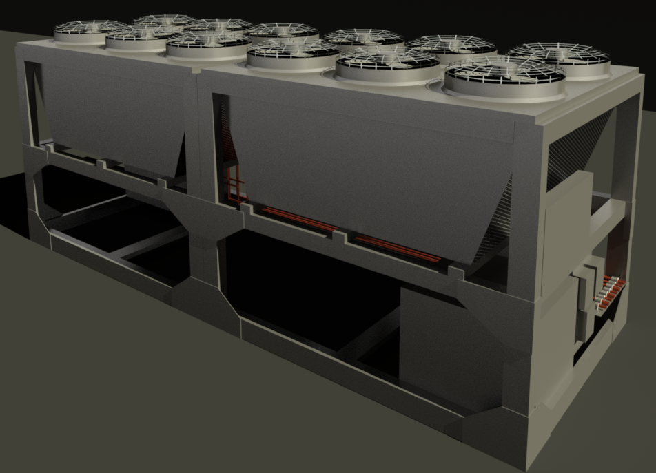
First out of the gate are a couple chilled water condensers, a 330kW unit and a 660kW unit. Both families have been modeled with three levels of detail in 3D and 2D, with materials from the Revit library applied to the 3D fine views. The use of 2D geometry (symbolic lines and masking regions) for 2D views ensures faster performance within a Revit project. They also include clearance zones set to a Clearance Zones subcategory, which gives the end user more control over visualization within their projects.

Although the two families have a larger than normal Andekan file size (800KB-1MB), this is largely due to the nature of this kind of equipment. Anything on a skid/frame raises complications, because you can see all of the internal components that can normally be ignored in a Revit family. Of course we simplifed the geometry for those internal components, but we kept enough detail for the Revit family to continue looking the part of the actual product.
The only nested element used in both Revit families are the fans seen on top. While the 660kW unit appears to be simply two of the 330kW units stuck together, there are some key differences in the piping connections involved. So the 660kW family does not have the smaller unit nested, which creates more work for us but ultimately produces a family that is faster to work with and has a smaller footprint.


This is also the first project where we created our own images for the materials. In the past, we have modeled geometry for a single fan, for example on air conditioner or heat pump Revit families. But since this family was already on the larger end of acceptable file size, we couldn’t justify the added file weight of having 2D and 3D for the fan detail. In answer to this problem, we created our own images for the fan image and fan bump image. This means that complex fan geometry doesn’t need to be created, instead just a simple extrusion to host the new custom material.

Although the fan images may not be visible in normal shaded mode, the fans will show whenever the user creates a render for the project. In order for you to see the fan image, he/she needs to copy the two custom image files to the correct material folder location on their c: drive. C:\Program Files (x86)\Common Files\Autodesk Shared\Materials\Textures\1\Mats.