System connectors and their limitations have been a recurring theme in a slew of MEP content projects that we’ve been working on recently. When it comes to creating Revit families for MEP systems (HVAC, piping, plumbing, electrical, etc.), connectors are an essential feature of any usable piece of content. Anyone doing system coordination and calculations in Revit projects will know about the importance of having families with the right kinds of connectors, and of having those connectors correctly configured for the particular system (and for those that don’t, you can check out this Autodesk primer on Revit connectors).
Still, when we think about what makes for complex MEP Revit families, we’re usually focused on how varied and intricate the model geometry is, or how to configure parameters and type catalogs to cover a range of technical options. It can be easy to underestimate the impact that system connectors can have on how you should build a Revit family.


In part, this is because system connectors in Revit have certain limitations that may not be obvious to engineers who use Revit families in projects, and even less so to manufacturers who hire others to build Revit families for their products. In terms of building MEP content in Revit, the three most critical constraints on connectors are:
- Connectors added to a family cannot be turned off – When you add a connector to a Revit family, that connector will be available to use no matter what else you do with the family. You can temporarily hide a connector’s geometry in a particular view, but the connector itself can’t be permanently hidden or deactivated.
- A connector’s discipline cannot be changed – Once you’ve designated a connector’s discipline (pipe, duct, electrical, etc.), the only way to change it is to delete the connector and add it again.
- Not all connector properties can be controlled via parameters – You can link certain connector properties to family parameters, but some big ones such as System Type and System Classification can’t be controlled that way. This has an impact in terms of covering system specs via type catalogs, and it generally makes it more difficult for end users to manage system connection details within a Revit family.

The big upshot of these limitations is that your fundamental connector options cannot change from type to type or based on other parameter values within a Revit family. This creates complications for certain kinds of MEP equipment that can be configured to have different numbers or types of connections based on their required capacity, application or other factors. Rather than being able to cover the full range of technical configurations within a single Revit model, the model has to be split into a separate .RFA files to reflect these different connector configurations.


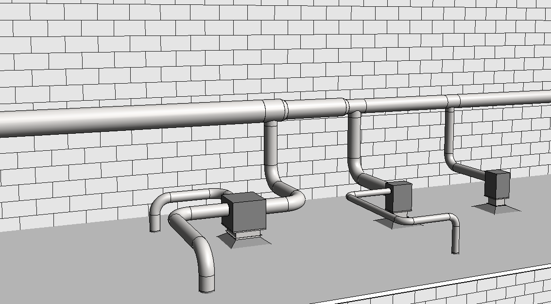
One might argue that it’s not very difficult to handle this situation – simply save another copy of a Revit family and then just change the connector options, right? To a degree that’s true, but of course the devil is in the details. It might not take much work if you have a very simple set of technical configurations that happen to require different number of connectors. We faced a situation like that with the ceiling radiation dampers shown above, where there could be between 1 and 3 connections for supply air, but the types of connectors were all the same and the impact on geometry was minimal.
Then again, it’s a different story when you’re dealing with things like commercial or retail HVAC equipment that can have an extensive range of operating capacities, electrical specs and system options that all relate to your connectors – including different types of connectors and where those connectors can be placed. In those cases, splitting a Revit family by connectors is no trivial exercise, if for no other reason than the extra care that needs to be taken in configuring the connectors and all related parameters. It can also involve modifications to the model geometry, depending on the product and manufacturer requirements.

The good news is that it is easy to solve for this problem. The only thing that’s needed is the full product documentation from the manufacturer, and perhaps a conversation with them about which options need to be covered within their Revit families. Unfortunately that’s often a process that can take a while or have unanticipated developments, as the people in charge of helping sell and market the manufacturer’s products (i.e. salespeople, digital marketing staff, etc.) might not be the people who handle its technical documentation and product engineering.
Sometimes there are gaps in communication, timing or resources between those areas within a company. In that case, the next best thing to having all of the documentation at your fingertips is to be able to explain why an existing Revit family can’t work for your particular application, or why it’s going to take longer and cost more to create Revit families that cover all of the system options that the products require, or why your company should address that gap and align teams more closely.
So the next time you’re requesting MEP content from a manufacturer or planning to create MEP Revit families yourself, remember to consider the limits of Revit system connectors and how they can impact your models. It’s often the case that, due to connector limitations, an MEP Revit family will need to be split in ways that don’t match up exactly with how the manufacturer packages or sells the product. And if you don’t plan for that upfront, you’ll only pay the price in time and resources later on.
Hopefully this blog post helps anyone facing such situations, and if so then I’ll be a happy writer. Stay tuned for more on system connectors soon. I plan to write a couple more posts about how we can maximize their use and flexibility within Revit families, despite their limitations.