Our latest Revit content giveaway is a generic chilled beam family.
What is a chilled beam, you ask?
In case you’re one of the 99.99% of people out there who’ve never heard of a chilled beam, let me briefly introduce this obscure-but-mighty piece of mechanical equipment.
In large scale, complex HVAC systems such as hospitals, airports or research facilities, chilled beams provide cold or warm air to an internal space/room. Chilled beams are often recessed within a ceiling, and they use convection to create air flow. First, warm air is induced towards the coils in the chilled beam, and then the cooled air falls into the room/space.
There are both active and passive chilled beams. An active chilled beam is similar to the standard passive version, but with the addition of a ducted air source. The ducted air mixes with the convection air, allowing for greater cooling/warming.
Geometry
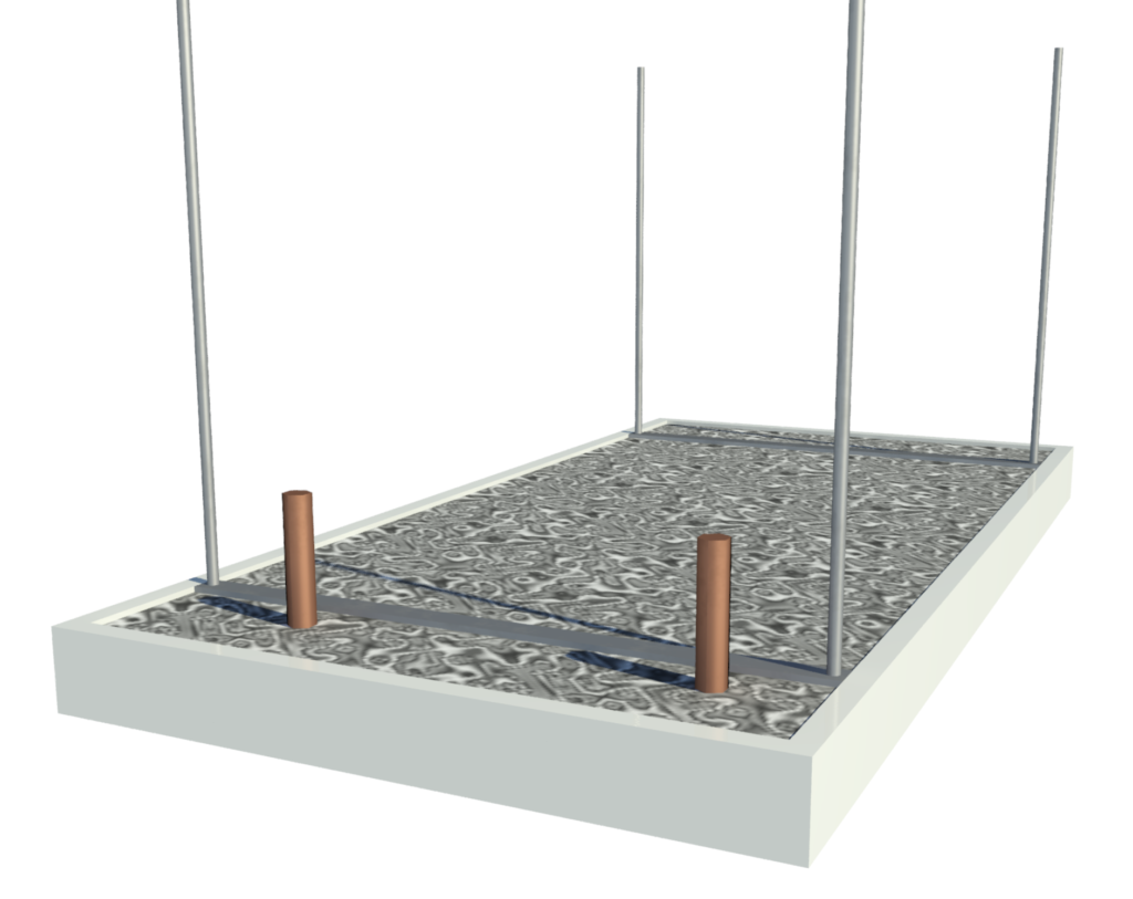
Based on manufacturer units from Flakt Group, Trox, Frenger Systems, Waterloo and Trane, our generic chilled beam family has three levels of detail in 3D and 2D. We restrict 3D geometry to only being visible in 3D views, allowing the 2D details to show in elevations and plan. While this is more labour intensive to create, the end user gets the benefit of being able to move and work faster in Revit.

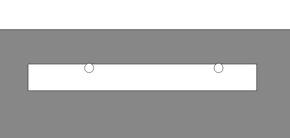
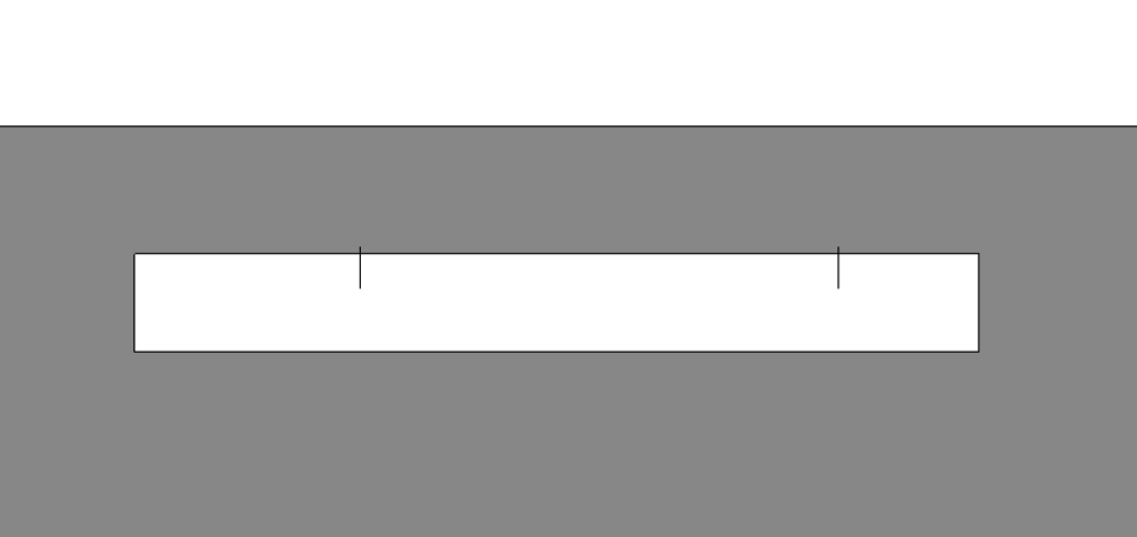
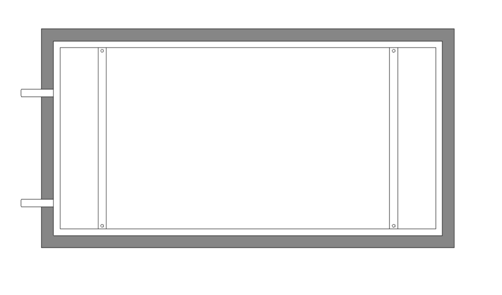
Fine 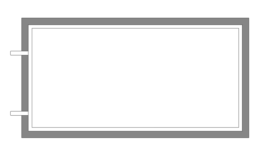
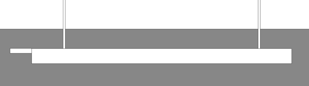
Medium 
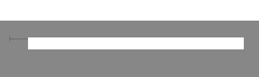
Coarse
The family also has five material parameters to control the appearance of geometries, including the main body, insulation, bracketry, pipe connections and clearance zones.
Flexibility
With a high degree of flexibility, the main body can change to any size. Likewise the pipe connections can change length and diameter, and have independent positioning from left, right and top of the unit. The pipe connections also have offsets from the bottom of the unit.
Equally important, the bracketry and drop rods can change position to ensure an accurate coordination of MEP services within the ceiling void. The corresponding drop rods can be aligned to a soffit level or any supporting structure, and therefore will stay connected during any changes in ceiling or slab levels.
The ceiling cutout also has independent parameters controlling it. This way, the generic family can adapt to suit a large range of manufacturer-specific models within limitations of geometry and file size.
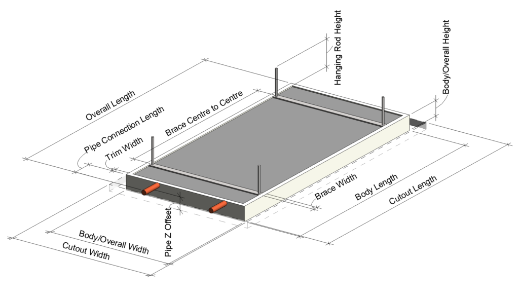
Parameters
Parameters controlling the visibility of model options are located under the Construction group. Parameters controlling the dimensions and setting out are located under the Dimensions group. All option parameters are type parameters, except for “Clearance Zone” which is located under the Constraints group.
While the model is intended to suit multiple variations by different manufacturers, there will always be instances where some work is necessary to transform the generic family into your desired manufacturer model. In such cases, refer to the parameters controlling formulas that are grouped under Other.
Options
The family includes the following option parameters:
- Clearance Zones – When selected, this activates the Clearance Zone geometry in 2D & 3D. The clearance zone geometry is assigned to a “Clearance Zone” subcategory, giving the user more control over its appearance.
- Threaded Rod Ceiling Hanging Brackets – Toggles the supporting drop rods on/off.
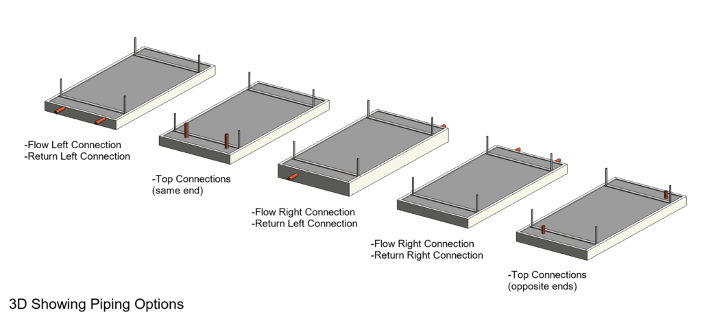
- Left/ Right Flow Connection – Two parameters that activate the left and right positions for the flow connector. The pipe z-offset will control their height.
- Left/ Right Return Connection – Two parameters that activate the left and right positions for the return connector. The pipe z-offset will control their height.
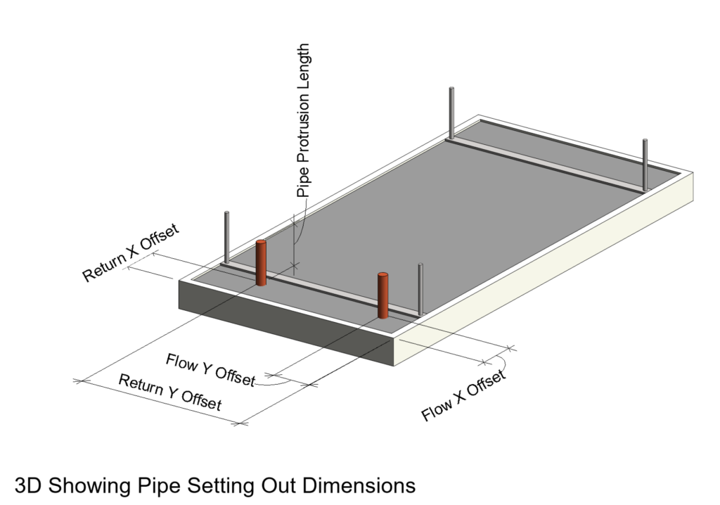
- Top Connections – Toggles the pipe connection to be on the top of the unit. The pipes x- and y-offset parameters decide where they go on this face.
How it’s built
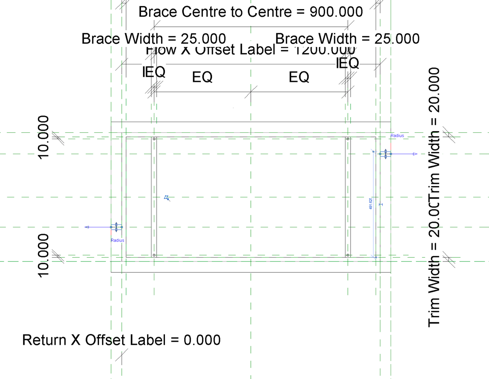
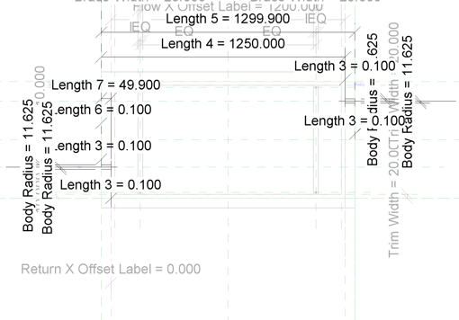
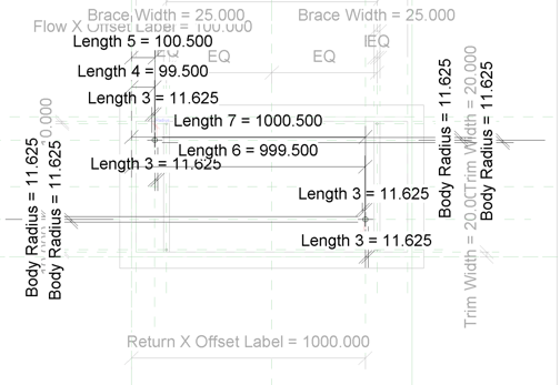
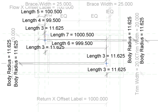
The family makes extensive use of reference planes and reference lines. All geometry and masking region lines are constrained to these to avoid any poor Revit flexibility. It is often the 2D elements that will break a family when flexing.
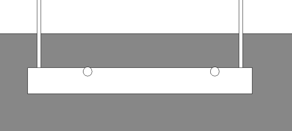
The pipe connections are hosted to independent reference lines, so that they can rotate about two axes to achieve the required positions. In plan view, this means we need to have 2D for both the horizontal and vertical pipe positions. In general, the more flexibility you have, the greater the impact there will be on your 2D views.
To simplify and minimize file size, we have combined these elements into one masking region by using a series of formula parameters, lines and ellipses.
Get the family
Our chilled beam family is available for free download for a limited time. We hope you enjoy using it in your projects, and we welcome any feedback or questions.
If you have an idea for our next content giveaway, send us a tweet or message us on instagram to put it in the running for our next free family.
Family Specs – Passive Ceiling-Recessed Chilled Beam
- Revit Version: 2017
- Category: Mechanical Equipment
- Hosting: Face-based
- Omniclass: 23.75.70.17, Water Heated and Cooled Terminal Heating and Cooling Units
- Manufacturer: Generic
- Units: Metric
- Types: 1 (built-in)
- Options: Left/Right Flow Connection, Left/Right Return Connection, Top Connections, Threaded Rod Ceiling Hanging Brackets and Clearance Zones
- Materials: main body, insulation, bracketry, pipe connections and clearnce zones
- Connectors: 2 hydronic pipe connectors
- File Size: 524 kb